Timing is everything, especially in serial communications. I’ve run into two interesting timing challenges on this project that need to be solved, but they couldn’t be more different. Check out part 1 first if you have no idea what’s going on.
Hooking up a real LCD
In part 1, we got the SPI data from the control pod, and used ANSI escape codes to recreate the display in a terminal window on my Mac. This is very cool, but not useful. I need to turn the Arduino into a translator that converts control pod serial data into parallel data for a replacement LCD, likely using the HD44780 protocol.

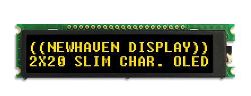
I ordered a slick, slim 2x20 character OLED for a replacement, but in the meanwhile, I have an old 4x20 CrystalFontz character LCD I can use to test my code and hookups.


It’s a parallel LCD, so we have 4 bits of data [D4:7], enable [E], and instruction/data register select [RS]. Since we’re starting with an HD44780-compatible display, I can simply use the Arduino LiquidCrystal library. Most of the commands from the control pod map directly to hd44780 commands, so I can either parse the commands, or just send the raw payload directly to the display. Here’s an example from the actual code.
    //payload is the decoded byte from the 3-byte serial sequences the control pod sends
    switch (payload) {
      case 0x01:
        Serial.print("\e[2J");
        lcd->clear(); //parse the command and send via library
        break;
      case 0x02:
        Serial.print("\e[1;1f");
        lcd->home(); //parse the command and send via library
        break;
      case 0x40:
        Serial.print("\e[2J");
        lcd->command(payload); //send the raw command
        break;
      case 0x0c: //turns on LCD, disables cursor
        lcd->command(payload); //send the raw command
        break;
    }
So basically the code works like this:
- The Arduino SPI interrupt adds any received bytes to the buffer.
- The main code loop processes the buffer whenever there are a multiple of 3 bytes in the buffer. (Remember that all data from the control pod comes in 3-byte sequences).
- For each 3-byte sequence, the main code loop performs the appropriate commands on the LCD.
- Once finished, the main code loop clears the buffer and waits for more data.
This is a simple solution that should work really well, right?
Gibberish problem
No, the solution was not so simple.
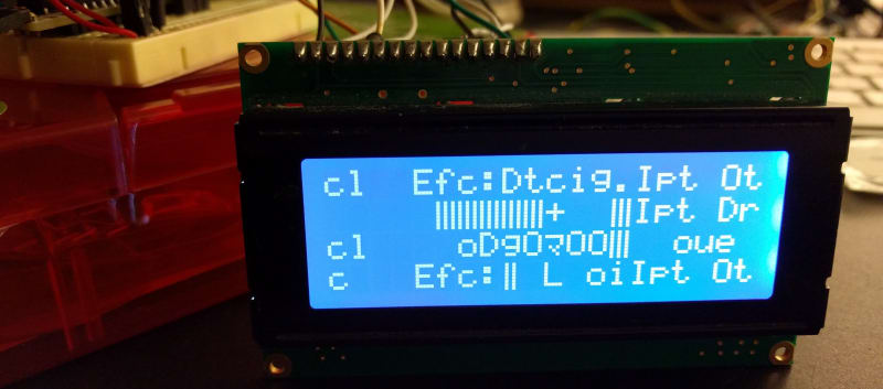
It’s supposed to say “Input: Optical” and “Effect: Detecting”. You can kind of see that.
This is a silly issue, but it drove me crazy for a little while. I did not really think about how the SPI interrupt and my main code loop interact. The interrupt can be called at any time, including when the main code loop is performing commands on the LCD. If I’m not careful, the main code loop can clear out the buffer without processing all of the data, because its state can overwrite more recent information coming from the interrupt function. This results in missing data. This could be missing commands or missing letters, and results in the gibberish you see above. This is a classic producer-consumer situation, and I can probably use a classic solution to get around it.
Gibberish solution
Ring buffers are the best solution I can think of. I used Steve Karg’s FIFO library for another project in the past, and fortunately he has an interrupt-friendly ring buffer available, as well. This library allows for objects of any arbitrary size, include our 3-byte sequences. As an added bonus, it’s lightweight, and it will use minimal space on our Arduino board.
The ring buffer changes the code like this:
- The Arduino SPI interrupt adds any received 3-byte sequences to the ring buffer.
- The main code loop pops an item off of the ring buffer and processes it.
- When the main code loop is finished it goes back to step 2.
In this way, the main loop is not responsible for clearing the buffer. This is enough to make sure no data is clobbered, and the SPI interrupt can safely add more data to the ring buffer any time it needs to.

Success! If only for some screens, we can now get data sent successfully from the control pod all the way to our own replacement display.
Custom characters problem
If the Z680 control pod just used standard letters, numbers, and symbols we would be done. Unfortunately, this is not so. The display uses custom characters for volume control and a few other functions, and those aren’t working with our new display yet.
How it works
When the control pod is first powered up:
- It enters standby mode. Speakers are off. LCD backlight is off. LCD power is on.
- Control pod initializes the LCD.
- It sends all of the data necessary to define the custom characters.
- It clears the LCD contents, and keeps the backlight off.
Only when the power button is pressed is control pod is turned on. Then the speakers turn on, the backlight turns on, and content is sent to the LCD for display. The LCD uses a 5x8 font, and supports up to 8 custom characters. Each custom character is defined using the lower 5-bits of an 8-byte sequence. There’s a nice breakdown of this here if you would like more information. I captured all of the data with my logic analyzer, so this breakdown might be helpful:


Why it doesn’t work
Like the gibberish problem, getting custom characters working also comes down to timing. The Arduino and OLED are both powered by the control pod, and the pod sends custom characters into CGRAM very quickly after it is plugged in and goes into standby mode. This is the only time it sends custom characters. We need to catch it quickly if we want to read that data, and unfortunately Arduino systems can take a long time to start running code after power on.


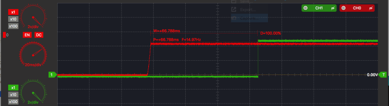
My oscilloscope shows we have about 125ms after power before the first bye of data is sent by the control pod. To see how long it takes Arduino to start up, I wrote a simple app that just sets a pin high. The RBBB Arduino starts after 1500ms!
Why am I using an oscilloscope instead of logic analyzer? Since I have to measure the 5V voltage rail, and Arduino expects at least 4.5V before it turns on, I need to see the analog values. If I used a digital logic analyzer, it might report every value above 3.0V as “logical 1”, which would make understanding the power behavior harder. Additionally, this way I can check for voltage dips during boot.
Solutions
The most obvious solution would be to hardcode the custom character information into my Arduino. But that would not be a ‘clean’ solution. I would never expect the control pod to send different custom characters, but I don’t care; if I’m solving this problem, I’m going to solve it right.
In that case, the only other easy solutions are:
- Replace the default Arduino bootloader with a faster one, like adaboot or optiboot.
- Reprogram the fuses on the ATmega328p on the board to start execution faster. The default is 65ms after power is applied, and it can be dangerous to execute sooner.
- Bypass the power stabilization components on the RBBB so that we can feed the ATmega328p with 5V sooner.
The bootloader seems like the safest option, and the one with the most potential gains. Lucky me, I still own an Atmel STK500. It is the AVR programmer that all other AVR programmers are based on, and it is exceptionally powerful, if a little dated.


Getting my STK500 to flash the bootloader was unpleasant. I’ll spare the details of each step. Contact me if you want to discuss any of them:
- Realize STK500 is so old it only supports v1 of the protocol, and can only be upgraded in Windows.
- Install Atmel Studio on Windows. Every time you try to upgrade STK500’s firmware, Atmel Studio crashes.
- Identify missing VC90 dll version and install.
- Upgrade STK500 firmware.
- Realize RS232 USB adapter kernel panics macOS 10.12.
- Install Arduino tools on Ubuntu.
- Edit Arduino system config so it supports STK500 high-voltage parallel programming.
- Install optiboot in Arduino app.
- Prepare STK500 for high-voltage parallel programming. Insert ATmega328p into STK500 slot 3.
- Burn optiboot bootloader onto chip, and put chip back into Arduino board.
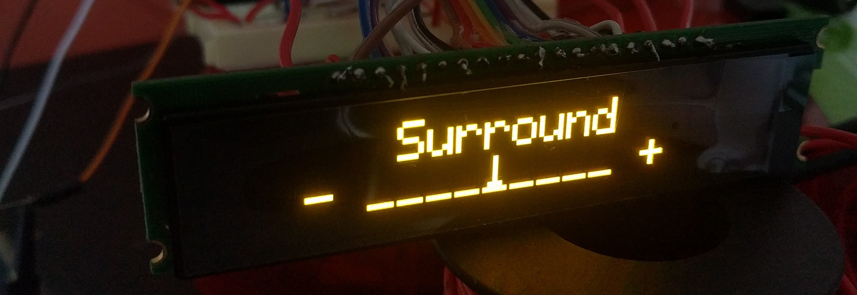
Amazing, just flashing optiboot reduced startup time from 1.5s to 65 milliseconds! Before trying anything else, I put my normal code back on the Arduino, and yes! The system starts up quickly enough to receive all of the CGRAM data from the control pod! Everything works! That’s how I took the yellow OLED pictures you saw earlier in the blog post.
Next steps & code
Code for this project is available as a GitHub repository. I created my own version of LiquidCrystal that is designed for the NHD Character OLEDs instead. It’s very messy and not ready for primetime. When it is, I’ll spin it off into a proper Arduino library with its own github repo.
The next step is figuring out exactly how to cram all of these electronics into the speaker control pod, in a way that works reliably and looks good. Maybe we can also get some bonus functionality. The character OLED datasheet has some neat features.
Who’s Varun?
I most recently was the founder of an HR tech startup, Disqovery. I have worn many hats, and I like making things. I also like talking business. You can reach me at smartperson@gmail.com, @smartperson, Github, and LinkedIn.